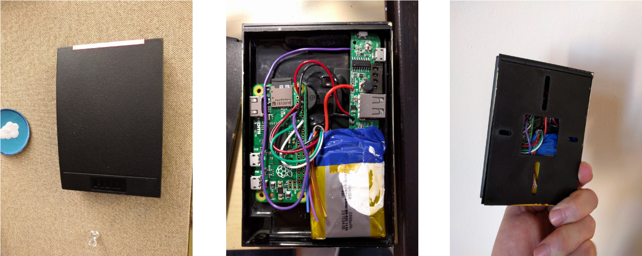
A while ago I came into possession of a few HID iClass readers. After collecting dust in my project drawer for a few months I decided to find a fun use for them, which ended up in the project I call Badgy.
Background
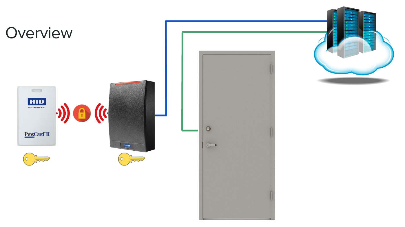
The back of the HID readers have 10 colored wires coming out of them. Luckily the readers also had a nice sticker telling me which wire was what.

The readers are nice enough to accept a wide range of input voltages to function from 5v - 16v. The readers speak the Wiegand protocol which is a simple and well documented protocol for sending bits over a wire.
Wiegand Overview
- Two Data lines (data0 & data1)
- Default to line high (~5v)
- Falling edge represents a single bit
- Variable bit length
- Test badges use 35 bits
- Noise can easily add extra bits on the line
- Use a well insulated wire
- Error checking can be implemented at a higher level if desired
- CRC or parity bit

I started off using an Arduino Wiegand library to read raw data from the card to prove the readers worked correctly. This allowed to me investigate the other non-Wiegand and power lines going into the reader. In short, the extra pins allow you to override the LED light color, beeper, and test the infra-red tamper sensor status (more on that later).
Card Code Format
The test badges I had use the Corporate 1000 data format. This format is used by most buildings that use the HID access cards. The format specifies parity bits, organization ID, and badge ID.


My test badges contain a 35 bit long code. The bit order for each organization can also be randomized for additional security via obscurity. With a large enough sample set of badges, identifying the bits that represent the organization ID can be trivial. (they will be the bits that are the same on all scanned badges for the same organization). The rest are for the individual badge ID and any parity bits used.
Encryption
The RFID information going between the physical badge and reader is encrypted, but the reader to the wire inside the wall is plain-text. The encryption keys used for the badge reader can be set by the organization that implements them, however most use the default keys from the factory.

This is not due to security negligence, but for functionality reasons. The badges and readers can only operate on a single key. So if two organizations, A and B, occupy the same building on different floors with a shared elevator system that requires a badge scan to operate, both organizations will need to use the same keys to allow both sets of employees to operate the elevator. Now suppose that organization B has another office somewhere else in the world and employees regularly travel between the offices. They want this office to use the same key to allow their employees to use one badge for all their buildings. If this second location is shared with organization C, then organization C will also need to use the same keys. So now organization C and A will be using the same keys even though they may not share any buildings. This can easily expand to hundreds or more organizations as each organization adds new offices and expands globally.
Cloning a physical badge (beyond the scope of this post) will require the private encryption key. The private key is stored in the HID reader in order to decrypt the response from the badge. Previous work has already been done to extract this key.
Replay
Now that the protocol and pins for the HID badge scanner are understood I wanted to see if it would be possible to use a micro-controller to emulate the reader to inject previously scanned badges into the system allowing a potential adversary access to a facility they have a badge code for but lack the physical badge at the time of entry.
The threat model here is the adversary has the ability to get the badge data but is unable to physically get the badge. Perhaps they scanned it while standing next to the victim on a crowded bus or by bumping into them on the street.
For this attack I used the same Arduino I used to read badges in the Background section but modified it so that the Arduino sends a pre-saved badge to whatever it is connected to. I could now send badge codes from one Arduino to another using one Arduino as a badge reader and another as the badge emulator.
The controller Arduino has no way to differentiate between the real HID reader and the Arduino acting as an emulated reader. In theory this will also work with the actual HID controller /access system, but unfortunately I do not have one to test on.
All is not lost, HID as thought of this and added a tamper line to the HID reader to detect someone disconnecting the HID reader, which is located on the outside of the secured perimeter. On the HID readers I tested, the tamper line is connected to an IR sensor located on the back of the reader next to an IR LED. The IR light bounces off a reflective sticker on the back of the mounting plate to detect if the reader is ever removed from the mounting plate.

However, this only applies to removing the sensor from the wall the way is was designed to be removed. If removed in what will likely be a more destructive way, it would be possible to access the tamper lines without triggering the tamper sensor allowing an adversary to connect into the line injecting their own “tamper OK” signal while disconnecting the real HID reader and connecting their micro-controller undetected. From here they can replay any collected badge codes or even attempt brute forcing access codes.
Building the Badge Collector

In order to easily collect as many badge codes as possible I wanted to create a self-contained badge reader. The badge reader should be self-powered, and have the ability to save collected badges to persistent storage on itself and ideally offer a means to transmit them wirelessly to a receiver nearby. I was able to accomplish all this and more with a Raspberry Pi zero and USB battery pack.
The wiring is as simple as connecting the data0 & data1 Wiegand pins to two of the GPIO pins of the Raspberry Pi, and connecting the 5v output of the USB battery pack to the power inputs of both the Pi and HID reader.
The Raspberry Pi runs headless Debian and a program that can be found here that listens for incoming badge codes and saves them to a log file on the Pi’s SD card.
Wireless Data Exfiltration
So far this badge collector will work great if hung next to an unsuspecting door. Employees are likely to scan badges to see if they will have access to this newly “secured” area. But if someone discovers it and removes the reader, what then? Aside from loosing the hardware, all the collected badge access codes are gone. Or are they?
The little known PiFm library allows Raspberry Pis to transmit over FM by bit-banging FM over GPIO pin 7. Using this we can convert the log data to audio using espeak and then send it to the FM transmitter provided by PiFm. All we need to do is attach a wire to GPIO Pin 7 to act as the antenna.
With this addition, every time a badge is scanned the data is logged to the Pi’s SD card and transmitted over FM where a nearby FM recorded can make a backup of the badge data.
