A while ago I received a bunch of bare ESP-WROOM-02 chips on tape, but I could not find enough documentation to program them (partially out of laziness). With my recent interest in ESPHome, I decided to give them another try. This blog post contains the results of my research on how to program them.
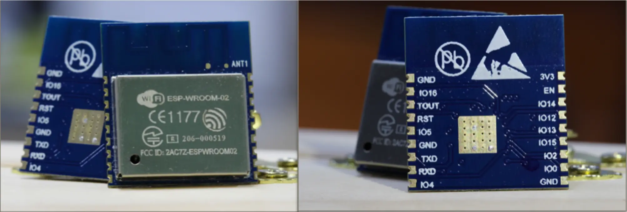
ESP-WROOM-02
The ESP-WROOM-02 is just a ESP8266 underneath. If you don’t have a breakout board like me, then you will need a UART adapter and make a few minimal solder connections to set the various boot modes to allow you to program the firmware. Once programmed for the first time, you can use OTA updates to allow flashing firmware over WiFi and not need to mess with the wiring every time you want to reprogram it.
The pinout of the ESP-WROOM-02 from its datasheet is as follows:
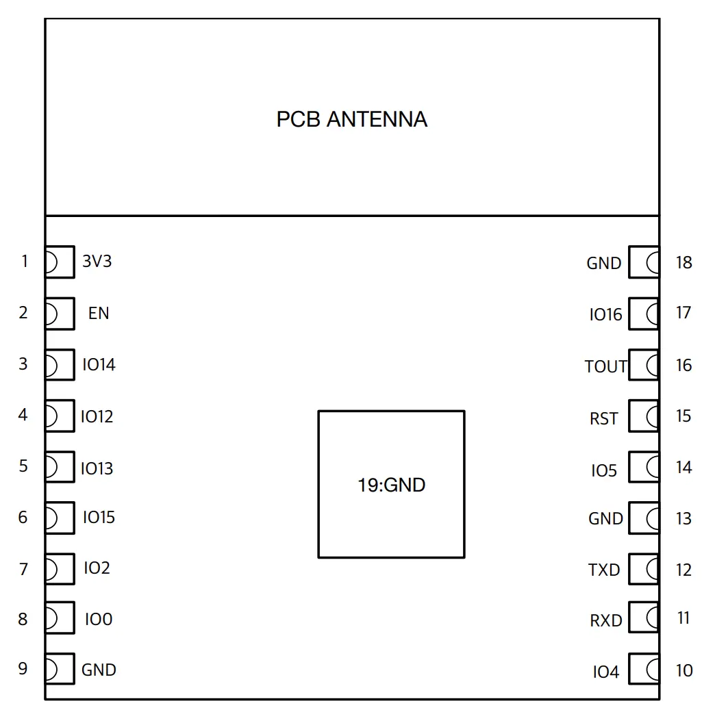
ESP-WROOM-02 pinout
Powering the ESP-WROOM-02
At a minimum, to power the chip, you’ll need to provide 3.3v to pin 1, and ground to pin 9 or pin 18. You’ll also need to pull the EN pin high to enable the chip. The correct way to do this is to use a 10k resistor between pin 2 and your 3.3v power source, but I just bridged pin 1 and pin 2 so that the ESP is always enabled when receiving power. This is a hack, but good enough for my purposes.
When the RST pin 15 goes from low (GND) to high or floating it will reset the ESP. This can also be achieved by reapplying power, so it is not strictly needed for programming but can be nice to have.
Boot modes
If you were to power on the ESP-WROOM-02 as described above and look at the serial output at 74880 8n1 you would see the following message from the boot-loader:
\xFF
 ets Jan  8 2013,rst cause:1, boot mode:(7,0)

waiting for host
The boot mode shows the current and previous boot mode as mode:(current, previous).
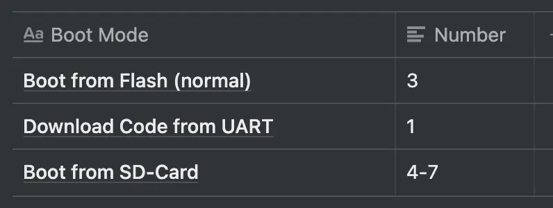
Boot Mode Table
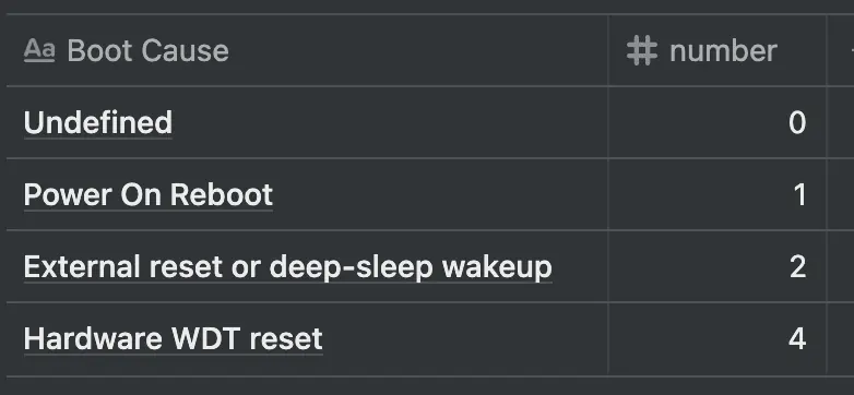
Boot Cause Table
We only care about booting from UART for programming and from flash for running the program.
In order to boot to UART for programming IO0 and IO15 need to be held low (GND) while the ESP boots up. Once in UART programming mode the ESP will switch to 115200 8n1 and wait for a program to be loaded.
To boot normally and run your flashed program IO15 needs to be held low (GND) and IO0 can be held high (with a resistor to 3.3v) or left floating.
After the ESP is booted (in either mode) IO0 and IO15 can be repurposed for other GPIO. They only need to be held high/low during boot to set the correct boot mode.
After programming is done, you may need to manually reset the ESP (with RST or reapplying power) and change the configuration to make it boot to the freshly programmed code.
To make things as simple as possible, if you don’t need to use IO0 and IO15 for your project, IO15 can be permanently wired to GND, and IO0 to a switch to GND to allow for easy programming.
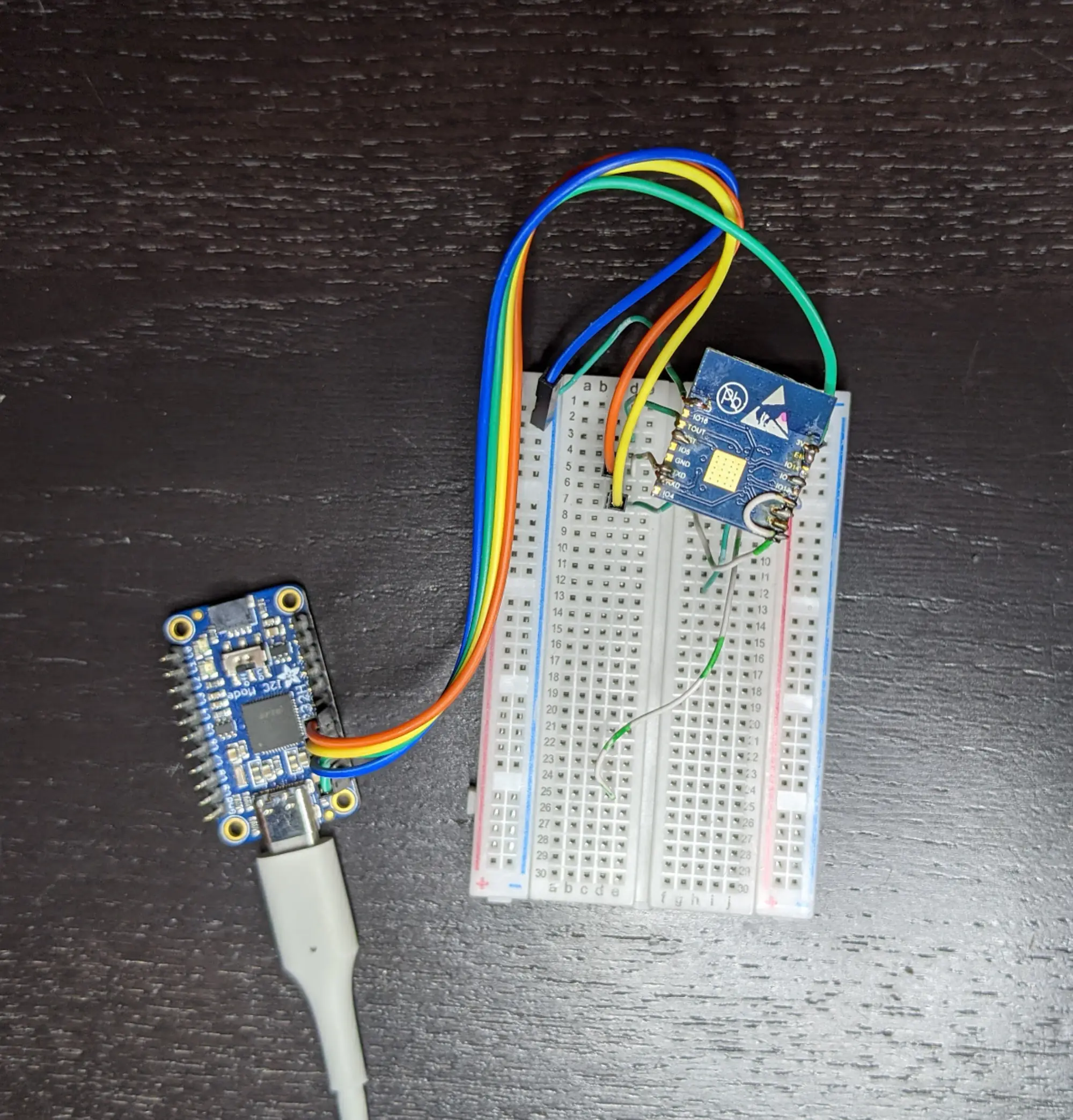
ESP-WROOM-02 breadboard setup with FT232H UART adapter
Photo of my ESP-WROOM-02 connected to an Adafruit FT232H UART adapter.
ESPHome
I’ve decided to use ESPHome as the framework to load code onto the ESP-WROOM-02, but it is also possible to use the much more lightweight Arduino ESP8266 framework as well. ESPHome can be installed inside Docker or with pip.
Below is a minimal ESPHome yaml configuration file to get the ESP online and configured to allow flashing further firmware updates over WiFi. Be sure to update the placeholder values with your own. You can also enable other sensors or integrations supported by ESPHome.
esphome:
  name: esphome-wroom-02
  platform: ESP8266
  board: esp_wroom_02

wifi:
  ssid: "YOUR_WIFI_SSID"
  password: "YOUR_WIFI_PASSWORD"
  # Enable fallback hotspot (captive portal) in case wifi connection fails
  ap:
    ssid: "ESP-WROOM-02"
    password: ""

# fallback mechanism for when connecting to the configured WiFi fails.
captive_portal:

# enable OTA for firmware flashing over WiFi
ota:
  password: "YOUR_SECURE_PASSWORD_HERE"

# Enable logging
logger:

# enable local web server
web_server:
   port: 80
When you are ready to flash your ESP-WROOM-02 with ESPHome, just pass the yaml configuration file as an argument to the ESPHome command after connecting your UART.
esphome esp-wroom-02-example.yaml run
This will flash the ESP-WROOM-02 with ESPHome with your settings and then start displaying the logs being sent from the ESP over UART. At this point it is now safe to kill the command and disconnect the UART.
Whenever you power on the ESP-WROOM-02 it will connect to your network and run the configuration you loaded onto it. If you ever want to flash an updated firmware, you can use the http server now running on the ESP to upload a new firmware (be sure to have it set to connect back to the same network) or use the same esphome run command without the UART connected to upload new firmware wirelessly. You can also use esphome logs to view the logs wirelessly without uploading new firmware.